The plant room, which contains the infrastructure that produces the heating, cooling, water softening and temperature regulation for the building, is a restricted site due to safety and hygiene regulations.
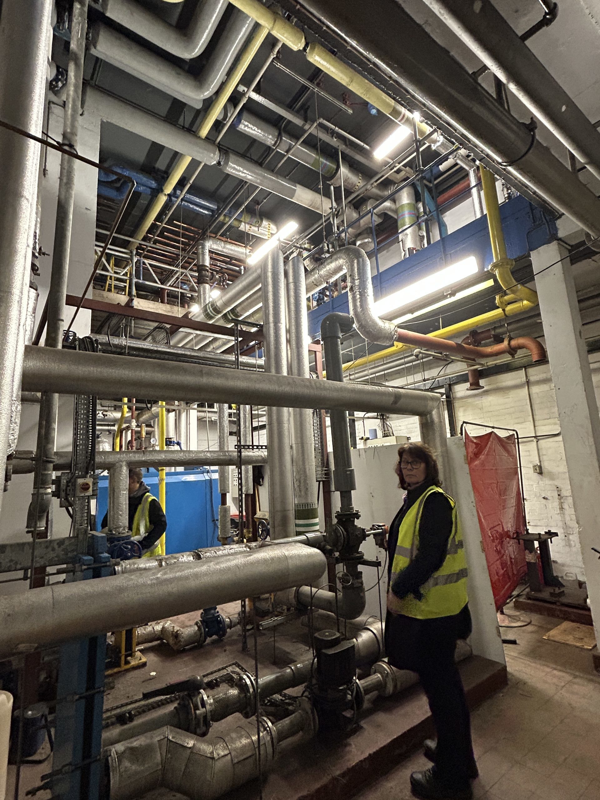
A “virtual tour” of those facilities, illustrated here, will give you a better understanding of the scale and intricacy of the existing infrastructure dating back to the 1960’s, which has required extensive and increasingly costly maintenance as parts of the system reach the end of their life-cycle. The obsolete components are now being replaced with contemporary energy-efficient modules which will significantly reduce our energy consumption and maintenance costs.
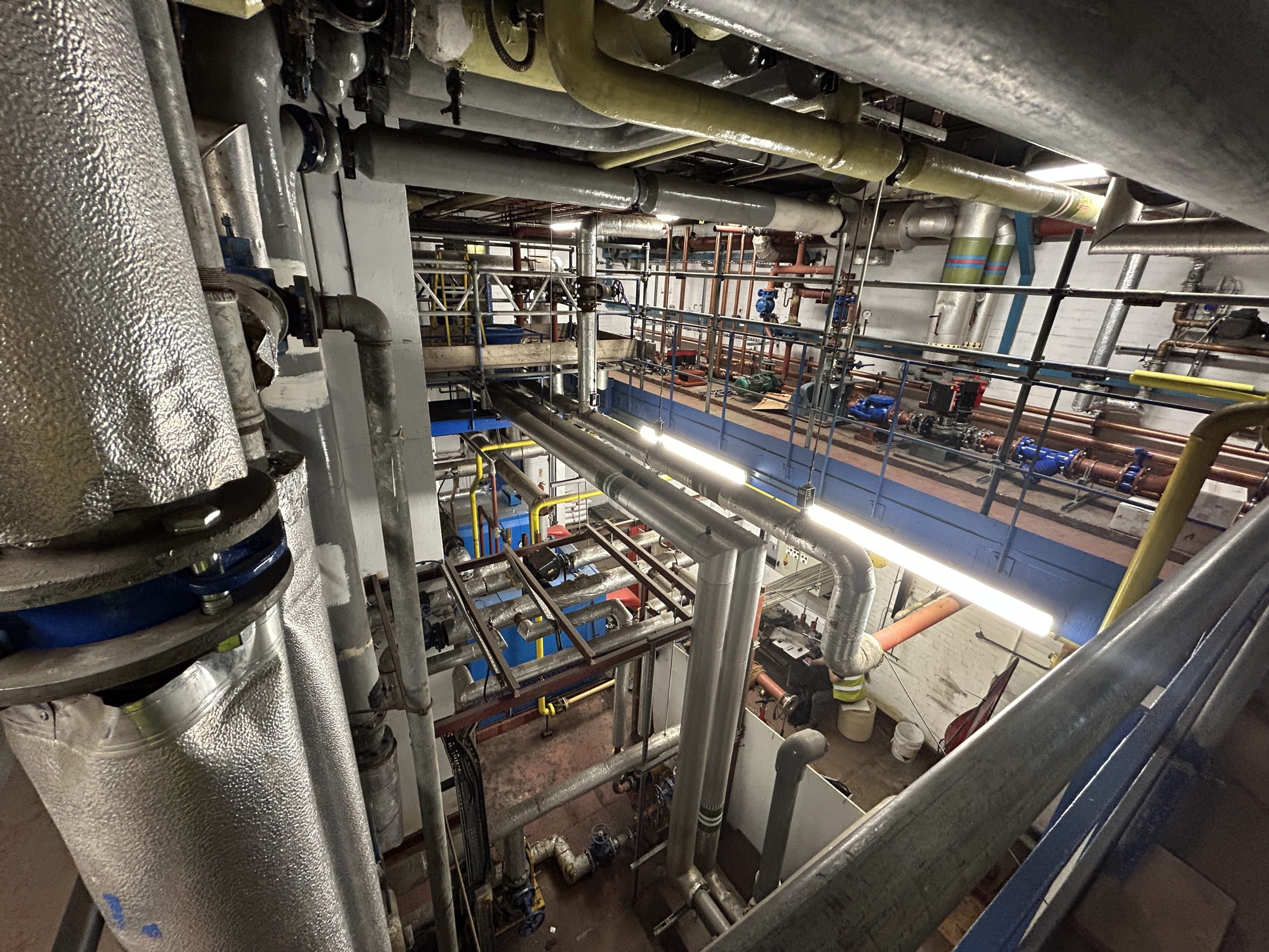
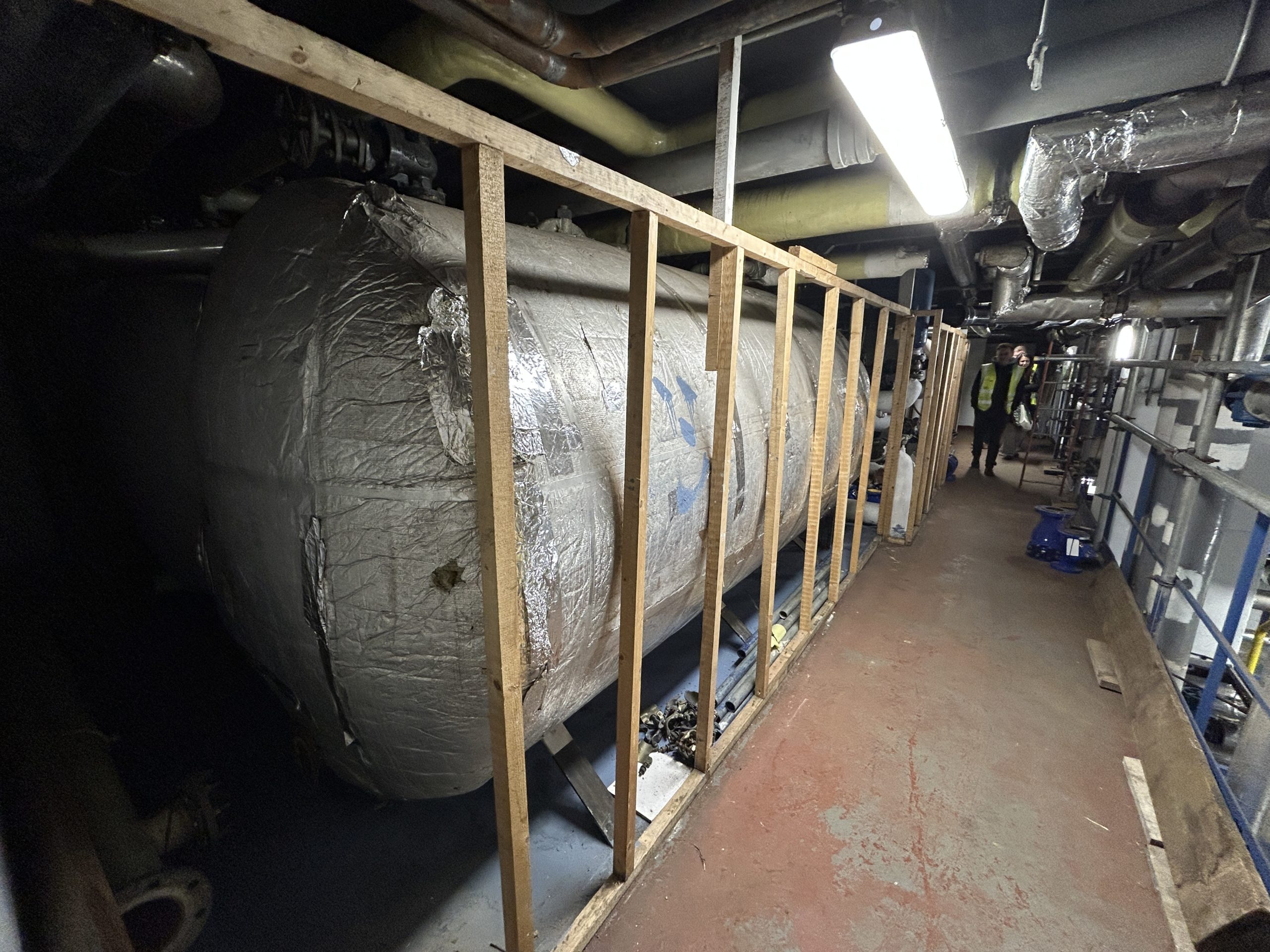
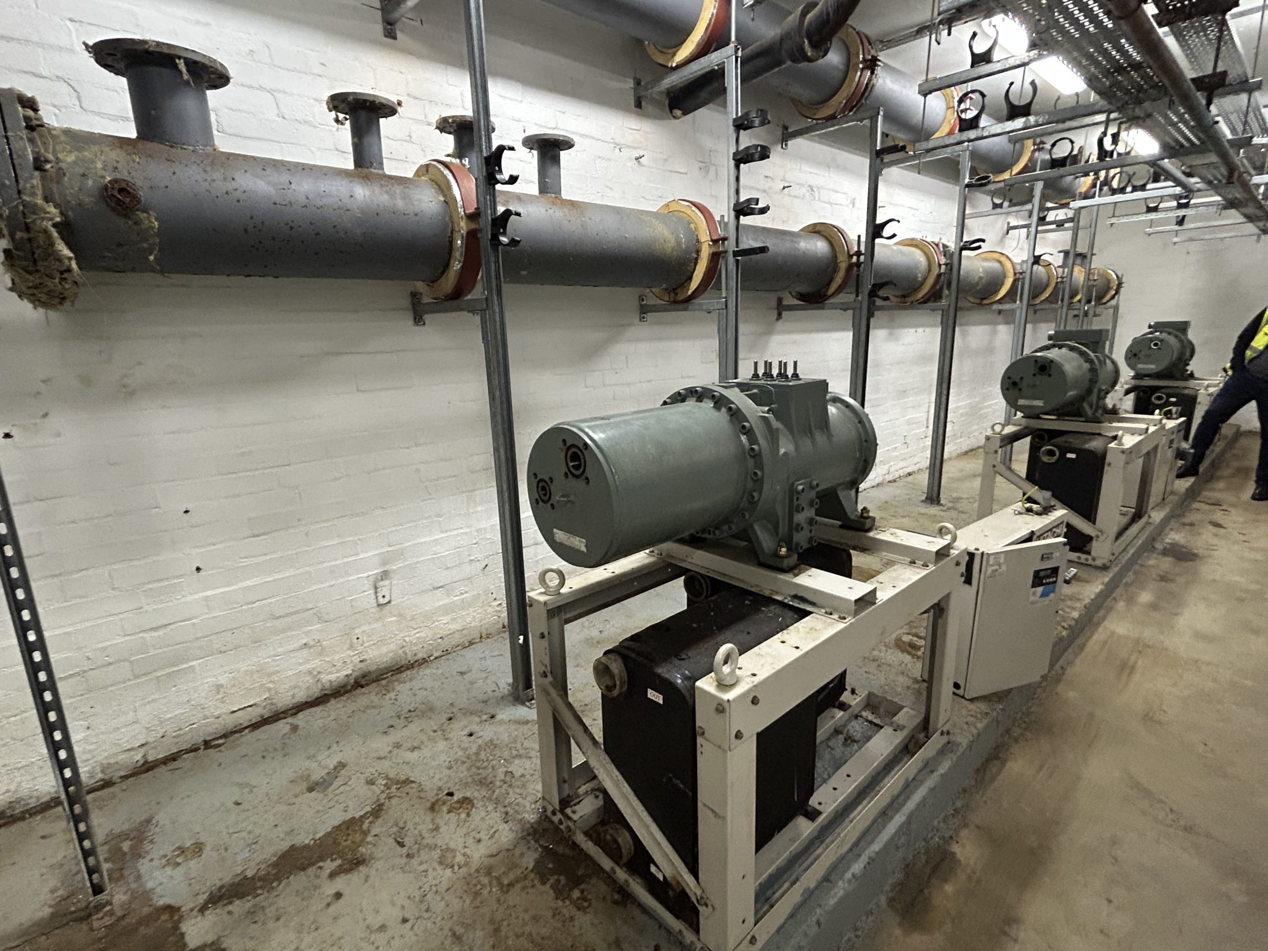
The vast space that houses the plant room occupies the equivalent of three floors beneath the level of our basement. That plant room comprises the gas fuelled burners that provide hot water and heating to the building, as well as large water tanks, control systems that manage the flow of heating or cooling throughout the building, and the old and now defective chillers that provided the building’s cooling since the 1960’s.
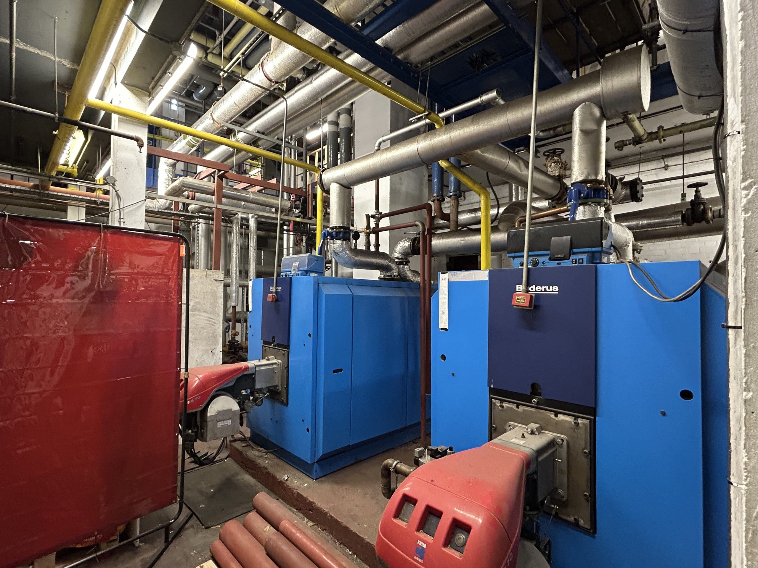
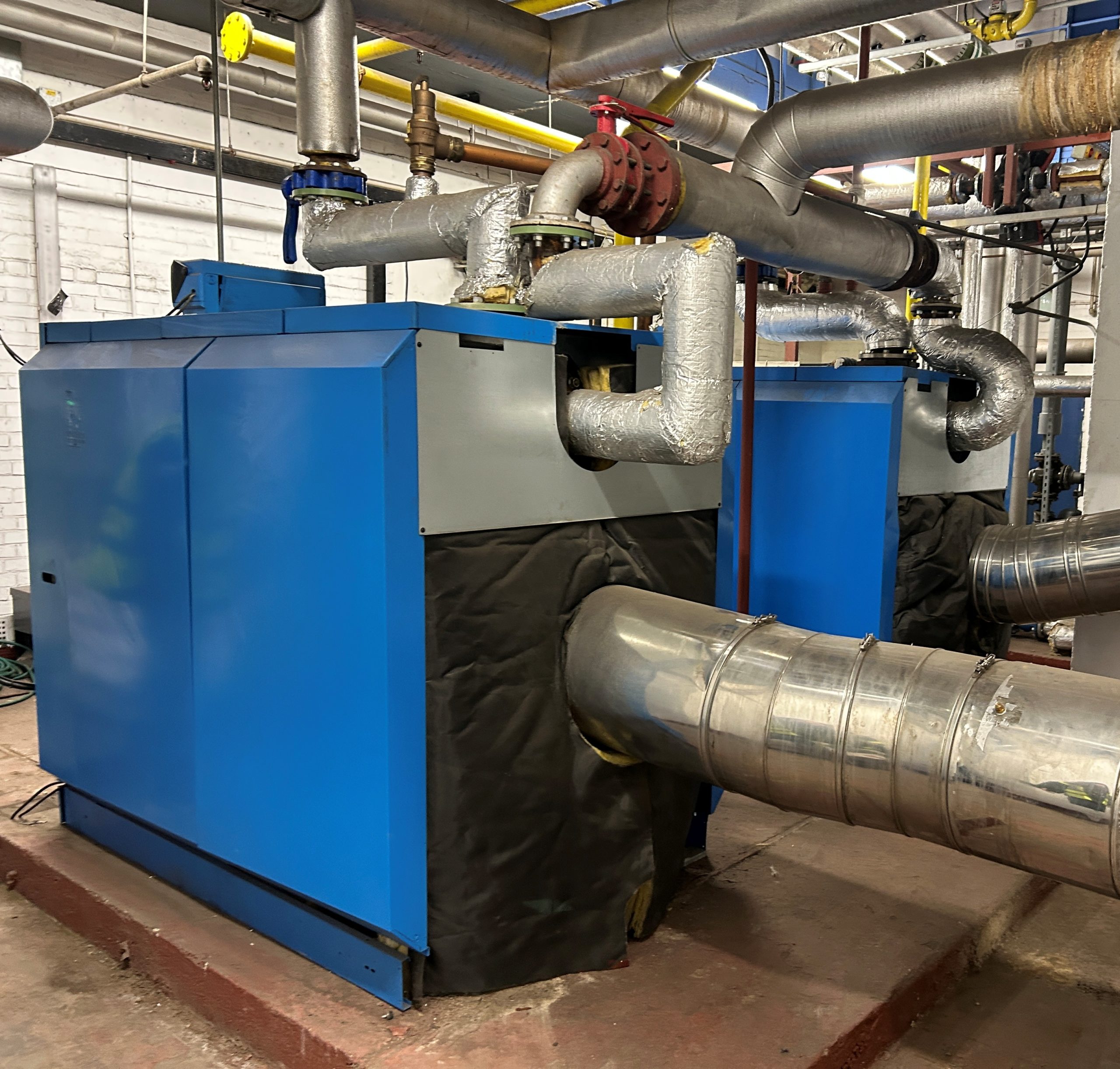
As the boilers and hot water tanks were replaced some years ago, we do not have any issues with the heating side of the system. The concerns we are addressing with the current refurbishment project relate to the efficient provision of cooling, the pipes that run through the building to feed the air convectors in each flat, and the air convectors themselves.
The overall design of the original system is complex because it involves numerous exchanges between the equipment located in the plant room beneath the building’s basement, and the elements that sit on the roof. This requires a maze of pipes; those located inside the plant room are mostly in good condition, as can be seen on these pictures. However, those that distribute the hot or cold fluid throughout the building show signs of significant corrosion due to their exposure to the elements and now need replacing.
Many of the new pipes that need to be installed are too large to be delivered to the plant room readily assembled. A welder based on the lowest level is in charge of manufacturing the specific parts and joins to connect the basic piping elements.
Making better use of the existing modules
The boilers and water tanks that were installed a few years ago are in excellent condition. The energy efficiency of the heat produced by these boilers will be greatly enhanced by replacing the corroded pipes that run from the plant room to the air convectors in each flat with fully insulated pipes, and replacing the old Weathermaster convectors with thermostatically controlled Jaga units, which will avoid the current waste that results from heating or cooling the entire building regardless of occupancy levels and the personal preferences of each resident.
Replacing defunct elements with new energy-efficient technology
This all starts with replacing the old chillers which were located in the basement. Over the past few years, during which alternatives to the existing system were being evaluated, the building’s cooling system was kept on “life support” with numerous repairs and mounting maintenance costs, for the sake of providing the building with cooled air until a replacement system could be proposed and approved at an Annual General Meeting vote. Numerous breakdowns caused an interruption of service, and therefore repeated inconvenience to residents, in spite of those very high maintanance costs.
The row of four chillers depicted here will be replaced with energy-efficient heat-pumps located on the building’s roof. This far more efficient way of providing cooling will no longer require the “cooling tower” of the existing system, which contains 1,000 litres of water and a mechanical fan belt to disperse the exhaust heat generated by the chillers. Over the past years, this cooling tower has been a source of recurrent problems and high water treatment costs, which we can save from now on.
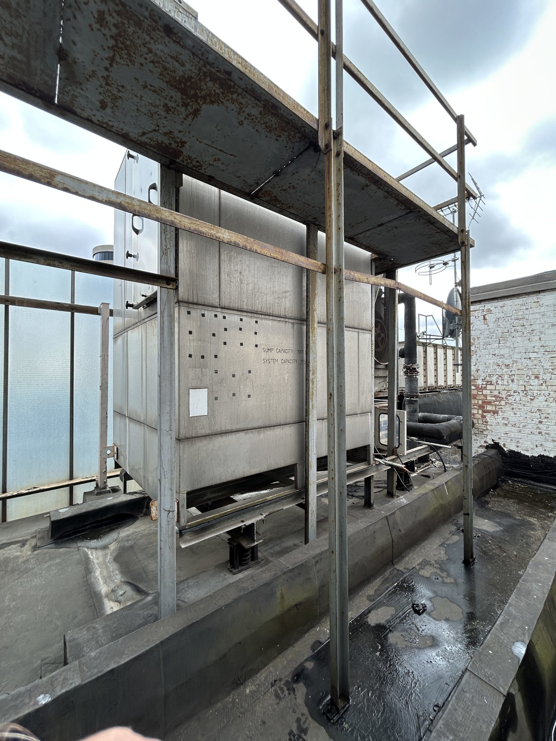
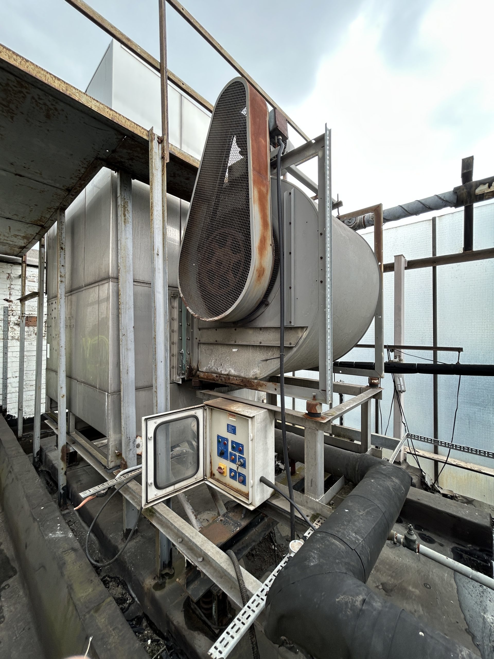
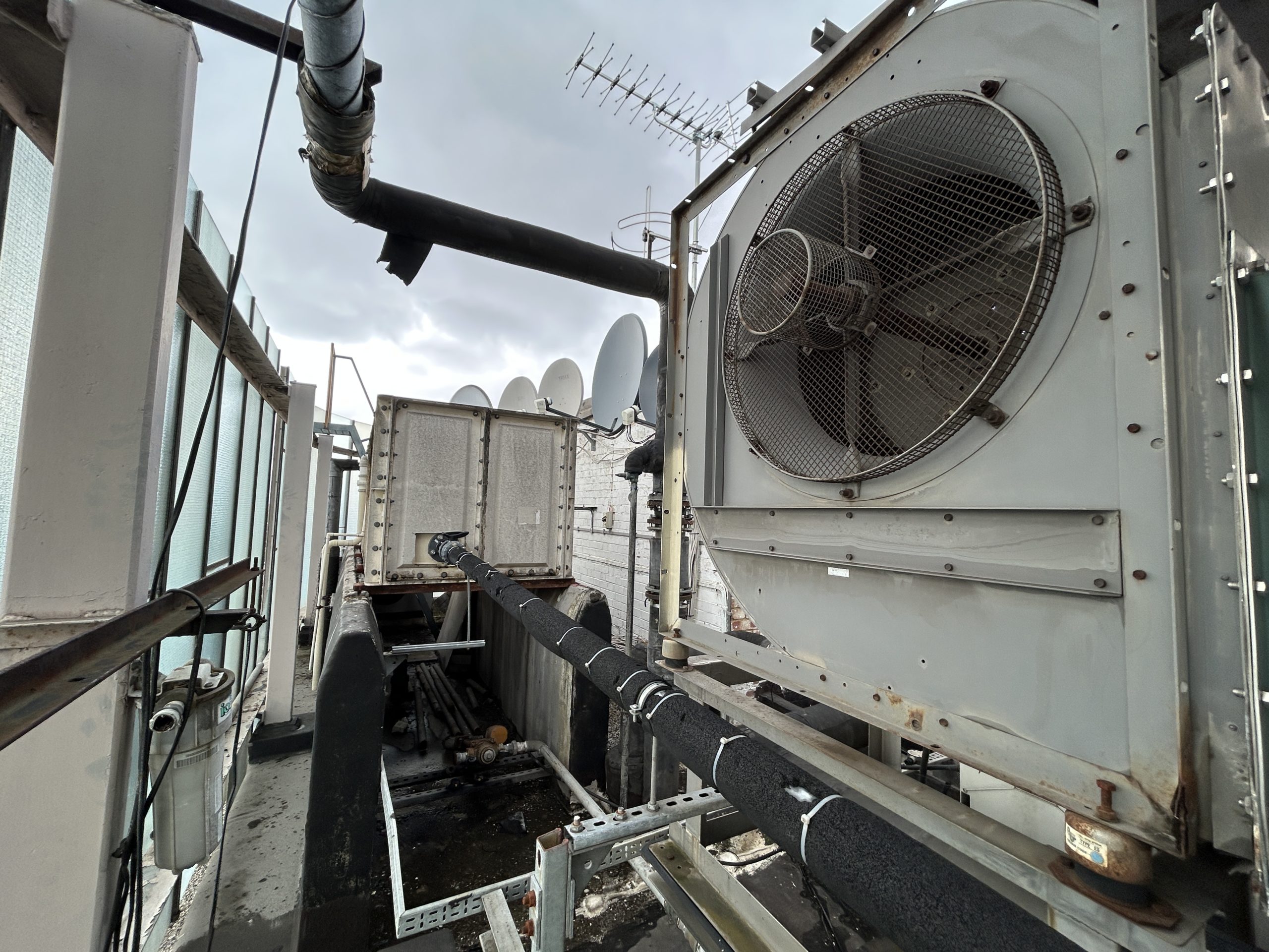
The new system will no longer require a “cooling tower” : this bulky equipment will be removed using the crane on the same day the new heat pumps and air handling unit will be hoisted up to the roof .
A glimpse of the work taking place below ground level in the plant room

Chiller room strip out works

Capper pipework installation

Intallation of heavy duty pipe to ceiling

Building Management System first fix commenced

Continued installation of pf pumps in basement

Removal of redundant Air Handling Unit pipe in roof plant room